Uncategorized files
Jump to navigation
Jump to search
Showing below up to 148 results in range #1 to #148.
View (previous 250 | next 250) (20 | 50 | 100 | 250 | 500)
 1964 Blue Bird Transit Home Brochure.pdf 0 × 0; 778 KB
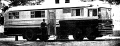 1964 Blue Bird Transit Home Photo.png 1,190 × 452; 156 KB
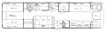 1964 Transit Home Floor Plan.png 2,650 × 814; 302 KB
- 1965Lubrication.pdf 0 × 0; 2.13 MB
- 1965Wiring.pdf 0 × 0; 841 KB
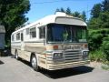 1965 exterior.jpg 640 × 480; 331 KB
 1966 Wanderlodge FC .png 902 × 700; 1.06 MB
- 1967 Wanderlodge Owner's Manual.pdf 0 × 0; 4.13 MB
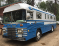
 1967 bluebird wanderlodge exterior photo.jpg 940 × 627; 181 KB
- 1968 Wanderlodge Data Book.pdf 0 × 0; 5.34 MB
 1968 Wanderlodge Exterior .png 912 × 454; 507 KB
 1969-blue-bird-wanderlodge-auction-by-water.jpg 1,920 × 1,080; 182 KB
 1971sp1.jpg 800 × 600; 88 KB
 1972FC.jpg 640 × 480; 166 KB
 1974.jpg 246 × 205; 10 KB
 1975 Wanderlodge FC.png 461 × 262; 191 KB
 1976 Wanderlodge FC.jpg 375 × 400; 48 KB
 1977 Exterior.jpg 1,024 × 765; 186 KB
- 1977 Wanderlodge Owners Manual.pdf 0 × 0; 3.32 MB
 1978 Wanderlodge FC.jpg 960 × 597; 209 KB
- 1978 Wanderlodge WLFC Owner's Manual.pdf 0 × 0; 3.81 MB
 1979-Bluebird-Wanderlodge-FC35.jpg 600 × 450; 48 KB
 1979 Blue Bird Wanderlodge.jpg 1,920 × 1,440; 574 KB
- 1981-1986 Wanderlodge Quick Reference Parts Catalog.pdf 0 × 0; 2.28 MB
 1981FC33-Figure 2-1.png 626 × 742; 671 KB
- 1981 FC 33 Owners Manual.pdf 0 × 0; 8.4 MB
 1981 FC 35 Example.png 460 × 328; 282 KB
 1988 WB Lower Dash Panel Diagram.png 1,353 × 608; 903 KB
 1989 WB40 - Figure 8-1.png 320 × 240; 64 KB
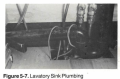 1989 WB40 Figure 5-7 Lavatory Sink Plumbing.png 334 × 220; 81 KB
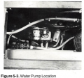 1989 WB40 Manual - Figure 5-3 Water Pump Location.png 322 × 300; 126 KB
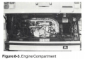 1989 WB40 Manual - Figure 8-3.png 333 × 232; 93 KB
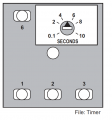
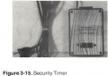 1989 WB40 Manual Figure 3-15 - Security Timer.png 325 × 231; 82 KB
 1989 WB40 Manual Figure 3-15 Security Timer.png 337 × 246; 83 KB
 1989 WB40 Manual Figure 3-16 - Bedroom Overhead Panel.png 1,193 × 255; 176 KB
 1989 WB40 Manual Figure 3-17 - Gas Grill.png 549 × 432; 285 KB
 1989 WB40 Manual Figure 3-18 - Co-Pilot's Control Panel.png 607 × 439; 143 KB
 1989 WB40 Manual Figure 4-1 - Typical Load Center.png 408 × 344; 152 KB
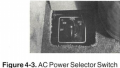 1989 WB40 Manual Figure 4-3 AC Power Selector Switch.png 314 × 178; 55 KB
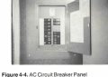 1989 WB40 Manual Figure 4-4 - AC Circuity Breaker Panel.png 368 × 261; 101 KB
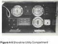 1989 WB40 Manual Figure 4-5 Shoreline Utility Compartment .png 401 × 309; 136 KB
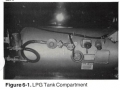 1989 WB40 Manual Figure 6-1 LPG Tank Compartment.png 344 × 257; 95 KB
 1989 WB 40.jpg 1,296 × 968; 162 KB
 1989 WB 40 - Manual Galley Photo.png 324 × 264; 90 KB
 1989 WB 40 - Steering Column Area Diagram.png 1,536 × 1,026; 1.54 MB
 1989 WB 40 Dinette Area Photo .png 311 × 255; 80 KB
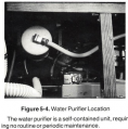 1989 WB 40 Figure 5-4 Water Purifier.png 315 × 319; 127 KB
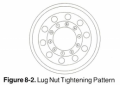 1989 WB 40 Figure 8-2 .png 259 × 184; 36 KB
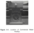 1989 WB 40 Manual - Figure 5-1 Water Hookup.png 329 × 316; 80 KB
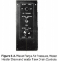 1989 WB 40 Manual - Figure 5-2 Water Purge and Drain Controls.png 295 × 308; 65 KB
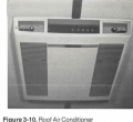 1989 WB 40 Manual Figure 3-10 - Roof Air Conditioner.png 343 × 315; 113 KB
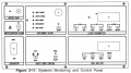 1989 WB 40 Manual Figure 3-11 - Systems Monitoring and Control Panel.png 605 × 340; 130 KB
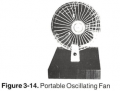 1989 WB 40 Manual Figure 3-14 - Portable Oscillating Fan.png 286 × 218; 45 KB
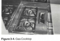 1989 WB 40 Manual Figure 3-4 Gas Cooktop.png 342 × 235; 92 KB
 1989 WB 40 Manual Figure 3-5 - Microwave Control Panel.png 722 × 534; 224 KB
 1989 WB 40 Manual Figure 3-6 - Food Center.png 330 × 259; 89 KB
 1989 WB 40 Manual Figure 3-7 - Toilet.png 350 × 259; 106 KB
 1989 WB 40 Manual Figure 5-5 Accumulator .png 310 × 295; 105 KB
 1989 WB 40 Manual Figure 8-4.png 395 × 336; 61 KB
 1989 WB 40 Manual Figure 8-5.png 470 × 307; 172 KB
 1989 WB 40 Manual Figure 8-6.png 446 × 309; 130 KB
 1989 WB 40 Manual Figure 8-7.png 480 × 376; 200 KB
 1989 WB 40 Manual Figure 8-8.png 446 × 335; 147 KB
 1989 WB 40 Manual Figure 8-9 .png 465 × 258; 150 KB
 1989 WB 40 Refrigerator Controls Manual Picture.png 617 × 386; 149 KB
 1989 WB Manual Figure 4-2 Battery Compartment.png 380 × 314; 133 KB
 1989 WB Shifter Panel Diagram.png 1,236 × 1,328; 681 KB
 1989 WB Upper Dash Panel .png 655 × 243; 101 KB
 1989 WB Upper Right Hand Dash Panel Diagram.png 1,546 × 586; 372 KB
 1989 Wanderlodge Brochure.jpg 612 × 370; 45 KB
- 1989 Wanderlodge Wide Body Chassis Parts Catalog.pdf 0 × 0; 12.92 MB
- 1989 Wanderlodge Wide Body Pusher - Owners Manual.pdf 0 × 0; 39.28 MB
 1990 WB 40 .png 6,000 × 4,000; 4.07 MB
- 1990 Wanderlodge Wide Body Chassis Parts Catalog.pdf 0 × 0; 3.08 MB
 73 Wanderlodge.png 1,420 × 1,158; 3.32 MB
 89 WB 40 - Pilot Overhead Dash Diagram.png 1,976 × 574; 606 KB
- 8V92TA Parts Diagram for engine model 8087-7B28.pdf 0 × 0; 2.24 MB
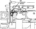 8v92 - Oil Pressure Sensor.png 544 × 446; 68 KB
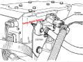 8v92 DDECI Turbo Boost Sensor.png 641 × 481; 129 KB
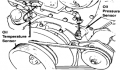 8v92 Oil Pressure & Temperature Sensor .png 326 × 191; 36 KB
 90wlwb towingjeep.jpg 4,032 × 3,024; 3.25 MB
- Allison Transmission Troubleshooting Manual TS2712EN.pdf 0 × 0; 52.77 MB
- Atwood Electric Water Heater.pdf 0 × 0; 340 KB
 CB Inverter control panel diagram - 89 WB 40.png 910 × 622; 294 KB
 DDEC I Schematic Diagram.png 956 × 706; 129 KB
- DDEC I TroubleShooting Guide.pdf 0 × 0; 22.29 MB
- Detroit-Diesel-Series-92-Engine-Service-Manual.pdf 0 × 0; 19.74 MB
- Detroit Diesel v92 Engine Wiring Schematics.pdf 0 × 0; 7.78 MB
 Drapery Control Install Figure 2 .png 338 × 506; 296 KB
 Drapery Install Figure 1.png 253 × 570; 245 KB
 Drapery Wheel Replacement.jpg 4,000 × 2,992; 3.23 MB
 Dupree Power Valve.jpg 3,927 × 1,956; 359 KB
 Dupree Power Valve Exploded Assembly.jpg 500 × 386; 22 KB
 Dupree Twis-Loc Manual Valve Exploded Parts Drawing.jpg 499 × 646; 53 KB
 Dupree Twis-Loc Valve .png 1,084 × 698; 360 KB
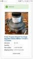 Fisher Propane Integral Two Stage Regulator R232A-BBFXA 1-4 Inlet x 1-2 Outlet .jpg 1,079 × 1,918; 161 KB
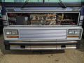 Front Electrical Wiring.jpg 4,032 × 3,024; 4.86 MB
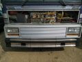 Front Exterior Wiring.jpg 4,032 × 3,024; 4.47 MB
- HWH Computer Leveling System v2.pdf 0 × 0; 5.81 MB
 HWH Leveling Jacks Paddle Switch Diagram.png 1,586 × 1,016; 801 KB
 LPG Regulator for 1989 WB 40.jpg 1,473 × 1,105; 185 KB
 La Gard Instructions Pg 1.jpg 459 × 816; 130 KB
 La Gard Safe Combination Changing Diagram.png 607 × 392; 318 KB
 La Gard Safe Dial Diagram.png 488 × 482; 64 KB
 La Gard Safe Instructions Pg 1.jpg 372 × 497; 90 KB
 La Gard Safe Instructions Pg 2.jpg 422 × 649; 125 KB
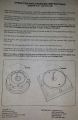
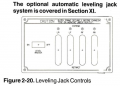 Leveling Jack Control Diagram.png 790 × 566; 268 KB
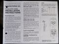 Lightwood Drapery Control Instructions.jpg 4,032 × 3,024; 2.72 MB
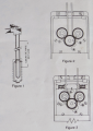 Lighwood Drapery Controls Installation Figures.png 746 × 1,054; 1.26 MB
 Lower Right Hand Dash Panel.png 1,930 × 920; 536 KB
 MN Mini Rally 2019.jpg 4,032 × 3,024; 1.24 MB
- Master Wiring, Chassis DDEC 1 8V92 1333566.pdf 0 × 0; 3.05 MB
 Microphor LF-220 Downward Discharge Diagram.png 2,398 × 696; 244 KB
 Microphor LF-220 Exploded Parts Diagram.png 1,678 × 1,334; 386 KB
 Microphor LF-220 Flush Cycle.png 1,274 × 468; 76 KB
 Microphor LF-220 Wiring Diagram.png 1,694 × 774; 122 KB
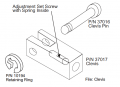 Microphor LF220 Adjustment Set Screw.png 554 × 402; 50 KB
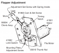 Microphor LF220 Flapper Adjustment Diagram.png 902 × 820; 164 KB
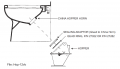 Microphor LF220 Hopper Diagram.png 1,078 × 616; 88 KB
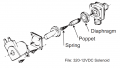 Microphor LF220 Solenoid Diagram.png 1,034 × 586; 98 KB
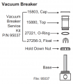 Microphor LF220 Vacuum Breaker Diagram.png 734 × 842; 90 KB
- Microphor Manual- LF-220 DC prior to 2005.pdf 0 × 0; 348 KB
 Microphor Water Level Adjustment .png 572 × 614; 40 KB
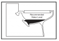 Microphor Water Level Diagram.png 710 × 490; 32 KB
 MusicalHornSongs.xlsx ; 15 KB
 Naming Convention Diagram 2.png 648 × 335; 29 KB
 NedSongs PMMI Horn List.png 756 × 846; 501 KB
 Ridewell Height Control Valve.png 586 × 269; 104 KB
 Ridewell Height Control and Dump Valves Example.jpg 466 × 340; 44 KB
- Ridewell Suspension RAD 227 Series Service Manual.pdf 0 × 0; 1.29 MB
 Safety Warning - Stand Placement.jpg 401 × 291; 52 KB
- SongCatalogbyAlpha03-25-03.pdf 0 × 0; 63 KB
- SongCatalogbyCategory03-25-03.pdf 0 × 0; 69 KB
 Test image.jpg 1,200 × 900; 161 KB
 Upper Front Passenger Side Wiring.jpg 4,032 × 3,024; 3.7 MB
 Wanderboy Logo.png 444 × 279; 15 KB
 Wanderlodge.jpg 4,032 × 3,024; 6.08 MB
 Wanderlodge Ridewell Height Control Valve Location.png 669 × 675; 306 KB
 Wikilogo.png 148 × 161; 6 KB
- Zip Dee Awning Owners Manual & Parts List.pdf 0 × 0; 1.37 MB
 Zip Dee Custom Contour Awning Operation.png 613 × 847; 220 KB
 Zip Dee Custom Contour Patio Awning Hardware Diagram.jpg 3,826 × 2,752; 432 KB
 Zip Dee Custom Universal Patio Awning Hardware Diagram.jpg 2,756 × 1,993; 270 KB
- Zip Dee Installation Instructions.pdf 0 × 0; 4.72 MB
 Zip Dee Uneven Roll Up Diagram (fig 15).png 570 × 295; 48 KB
 Zip Dee Universal Awning Operation Diagrams.png 586 × 871; 124 KB


.png)
